Non Destructive
Testing

Sitas Non Destructive Testing Services

Radiographic Testing

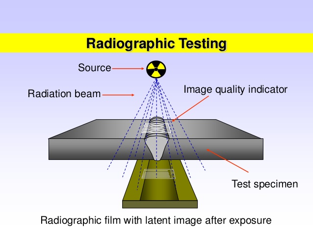
Radiographic Testing (RT), or industrial radiography, is a nondestructive testing (NDT) method of inspecting materials for hidden flaws by using the ability of short wavelength electromagnetic radiation (high energy photons) to penetrate various materials.

Ultrasonic Testing

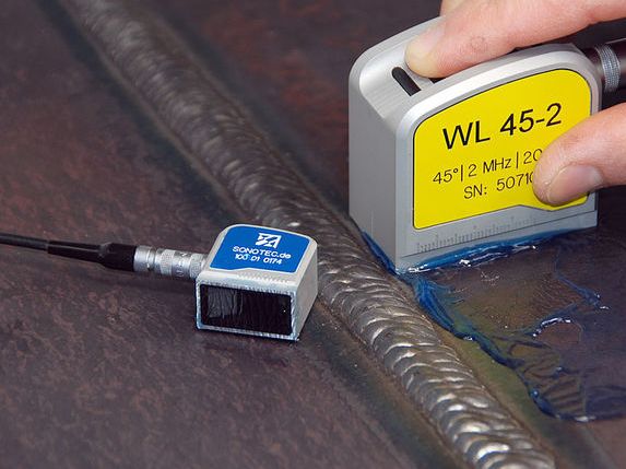
High-Frequency sound waves are sent out at a material to find material changes. A pulser produces an electrical pulse that causes a piezoelectric transducer to send out a sound wave. Reflected waves are transformed back into electrical signals by the transducer and analyzed. Applications are in thickness gauging and flaw detection

Magnetic Particle Testing

Magnetic Particle Inspection (MPI) is a non-destructive testing (NDT) process for detecting surface and slightly subsurface discontinuities in ferroelectric materials such as Iron, Nickel, Cobalt and some of their alloys.

Penetrant Testing

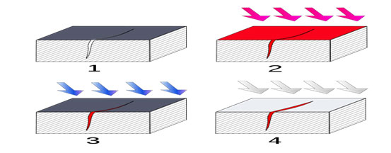
Dye penetrant inspection (DPI), also called liquid penetrant inspection (LPI) or penetrant testing (PT), is a widely applied and low-cost inspection method used to locate surface-breaking defects in all non-porous materials (metals, plastics, or ceramics).

Visual Testing

It is one of the most common and most powerful means of non-destructive testing. Visual testing requires adequate illumination of the test surface and proper eye-sight of the tester.

Upgradation Services

SITAS has full-fledged facilities and qualified welders for up-gradation of carbon steel, alloy steel and stainless steel castings. Radiographs will be evaluated to the required standards immediately and repairs / up-gradation will be undertaken.

Infrastructure

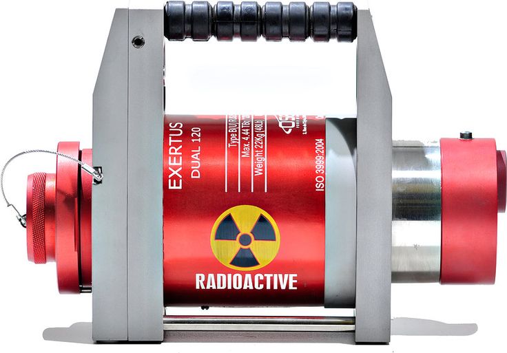
COBALT - 60 EXPOSURE DEVICES

  • Co-60 Model 684
  • Co-60 Model 680
  • Co-60 Model Sentry 110
  • Co-60 Model Sentry 330

IRIDIUM -192 EXPOSURE DEVICES

  • Delta 880
  • Roli-2

X-RAY EQUIPMENTS

  • Rich Seifert Model Eresco 200MF4-R
  • Rich Seifert Model Eresco 260 kva
  • Rich Seifert Model Eresco 280 kva
  • Super Liliput Portable unit Monotank 180 kva
  • Escorts Andrex 260 kva /300 kva
  • Luminux TF-3125 Portable unit 250 kva

LINEAR ACCELERATOR DEVICES

  • Linatron M6 – 6 MeV

SELENIUM 75 EXPOSURE DEVICES

  • 1075 SCARpro

Phased Array Ultrasonic Testing

  • OmniScan X3
  • Focus PX Acquisition Unit | Focus PC Software & SDK

ULTRASONIC INSPECTION EQUIPMENTS

  • USM 36 Ultrasonic Flaw detector with DAC/TCG/DGS
  • Kraut Kramer USK-7
  • Panametrics Epoch-III Model 2300
  • UFD Einstein-II (TFT)

MAGNETIC PARTICLE
INSPECTION EQUIPMENTS

  • Flaw Check Defectoscope Type UFHD-403 Bed length
  • Magnaflux Model P-1500 Prod Type
  • Magnaflux Model Crack Detector Yoke Type MEY-2

PERSONNEL MONITORING DEVICES

  • RADIATION SURVEY METERS
  • MINIRAD WIDE RANGE 0-5 mR/hr
  • MINIRAD
  • DOSIRAD SE-5 1-200 mR
  • POCKET DOSIMETERS
Scroll to Top

Principle of Radiographic Testing

Radiographic Testing (RT), or industrial radiography, is a nondestructive testing (NDT) method of inspecting materials for hidden flaws by using the ability of short wavelength electromagnetic radiation (high energy photons) to penetrate various materials.

The part to be tested is placed between the radiation source and a piece of film. The part will stop some of the radiation. Thicker and more dense area will allow less radiation to pass through. The property of the film will vary with the amount of radiation reaching the film through the test object. These differences in “absorption” can be recorded on film, or electronically.
The energy of the radiation affects its penetrating power. Higher energy radiation can penetrate thicker and denser materials. The radiation energy and/or exposure time must be controlled to properly image the region of interest.

Gamma rays are similar to X- Rays except that they have much shorter wavelength and differ in their origin. Gamma rays are emitted from the nucleus itself during the process of radioactivity. Gamma rays are produced by a radioisotope. A radioisotope has unstable nuclei that do not have enough binding energy to hold the nucleus together. The spontaneous breakdown of an atomic nucleus resulting in the release of energy and matter is known as radioactive decay.
Most of the radioactive material used in industrial radiography is artificially produced. This is done by subjecting stable material to a source of neutrons in a special nuclear reactor. This process is called activation. Two most commonly used gamma ray sources in industrial radiography are iridium 192 and cobalt 60.

Cobalt-60 is a preferred source for the radiography of steel thickness of about 75mm to 200 mm. We have world’s latest and sophisticated gamma ray projectors and proud to say that we are the only private agency in India having a maximum number of Cobalt -60 (TECH OPS) exposure devices.
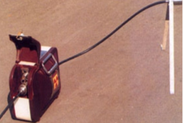
COBALT-60 EXPOSURE DEVICES

  • Sentry 110
  • Co-60 Model 680
  • Co-60 Model 741

Iridium -192 is used for radiography of steel thickness of about 6mm to 75 mm. We have Exposure devices (SPEC2T & TECH OPS) that are all imported and the latest.

IRIDIUM-192 EXPOSURE DEVICES

  • DELTA-880 Model
  • Tech – Ops – Model 660
  • Roli – 2

Betatron is basically a combination of an electromagnet and a transformer designed to guide and accelerate electrons in a circular orbit to very high energies. The toroidal type of hot cathode high vacuum X-ray tube commonly used in betatron is capable of injecting and energizing electrons to many millions of volts before striking the target to produce X ray.

Betatron of this type have been constructed to generate X-rays at energies ranging from 15 to 100MeV.The average beam current is on the order of 1A to 3A.The Focal spot of the target is usually less than 1mm(0.04in) in diameter. Commercially available betatrons are capable of radiographing steel in the range of 5mm to 41 mm.

Varian Medical Systems (NYSE:VAR) is introducing a new, portable industrial linear accelerator—a high-energy X-ray generator for industrial applications—that is powerful enough to penetrate steel, concrete, or other materials yet small and light enough to be easily moved from place to place. The new Linatron® Xp can be integrated into imaging systems for pipeline testing, perimeter security, vehicle inspection, and many other infrastructure inspection and first responder applications.

Varian offers both liquid-cooled and air-cooled versions of the Linatron Xp depending on the environment or the application. “The liquid-cooled version is for what we call ‘high duty’ applications, where you need to keep the X-ray beam on for longer periods of time. It is designed to run continually without having to stop for it to cool down—for example, when performing routine inspection of oil or gas pipelines,” Drubka said. “The air-cooled version is designed to be used in short bursts, with thermal recovery periods in between—like when checking out a package in the context of a bomb threat.”

Designed for quick setup and teardown, the Linatron Xp weighs less than 250 pounds—roughly 1/10th the weight of a full-sized industrial linear accelerator. It fits into two cases that can each be moved by two people. It is easily integrated with Varian’s PaxScan 2530HE flat-panel digital image detector, or it can be built into systems using computed radiography or film for fast, real-time digital imaging.
“The Linatron Xp fills a void in the marketplace, because there is no other compact solution that operates at high energy—between 0.95 and 1.35 megavolts, which is right in between the energy of an X-ray tube and a full-sized industrial linear accelerator,” Drubka said. “It also operates at a wide range of temperatures and, unlike other technologies, utilizes no cobalt sources, so there’s no radioactive waste to dispose of or to possibly fall into the wrong hands and turn up in a dirty bomb.”
The Linatron Xp is manufactured in Varian’s ISO 9001 certified manufacturing facility. It is an extension of the technology behind the company’s proven high-energy Linatron accelerators for non-destructive testing, inspection, security, and cargo screening applications.

OVERVIEW:
The advent of Proposed Linac X-Ray Machine source of very high energy x-rays has opened up inspection possibilities in a wide range of environments. Applications have included such areas as Gas/Petrol pipelines, shutdown projects, huge castings, industrial equipment’s, nuclear waste containers, Thermal power plants, space launch systems and other thick section problems that cannot be imaged using with other existing NDT equipment’s and similar methods which is available with us.

ADVANTAGES OF THE PROPOSED LINAC “M3A DUAL ENERGY X-RAY DEVICE”:-

HIGH OUTPUT
The output of Proposed Linac “M3A Dual Energy X-ray device” can carry out radiography from 31 mm to 230mm thickness. This gives the user great latitude for developing exactly the system to meet his needs without the large price differences normally associated with an increase in output.

THICK SECTION PENETRATION
As with output, the Linac “M3A Dual Energy X-ray device” system can match the penetration capability of fixed units in all respects. An important thing to remember is that these energies have never been available in the field before the appearance of these accelerators. That means otherwise un-inspectable areas can now be considered as candidates for NDE examination. For
instance, up to 230mm pre-stressed Huge Castings with defect indications can now be examined.

SHORT EXPOSURE TIMES
The very short exposure times, most commonly a few minutes or less, characteristic of accelerators make them much less sensitive to effects such as vibration or ambient radioactivity that limit other work. Radiation perimeter control is likewise made much easier and safer because of the very short exposure times. Further compare to the existing machines of cobalt 60 source device, the exposure time will be reduced enormously, for example if we take radiograph 180mm thick with cobalt 60 source device, to take for 1 exposure, it consumes 4 hours exposure time, by using for the same parameter with Linac X-ray machine, it will be 8 minutes per exposure.

IMAGE QUALITY/RESOLUTION
In addition to the shorter exposure times and high energy/output, this can give a higher sensitivity and finer film resolutions other than existing technology which is available with us, which will help us to interpretation more rapidly.

NO DECAY FACTOR FREQUENTLY
Frequently we are sending IR 192 device and Co-60 device to Board of Radiation and Isotope Technology to refill the powerful source, in this connection Co-60 device having decay factor frequently. In this technology there are no decay factors.

CONCLUSIONS
The experience of Caltrans has shown the portable linear accelerator to be a safe and effective method for radiographic inspection of a wide and huge shutdown projects. The consideration of this technology is recommended for those faced with the examination of large thick section structures that would otherwise defy analysis.

PRODUCTION RELATED ADVANTAGES

Now a day, NDT is mandatory on industrial components and similar shutdown projects, and its increasing customer base. The most of major customer’s demand for instant results, the proposed Linac Machine will help us to furnish the same within stipulated time, where it is difficultly to serve the customer needs with existing technology.

At present this technology is not yet implemented by any NDT industries in South India, henceforth; the major customer base will be increased as well as sales. The export customers are orally demanding to implement this technology. The additional benefits of the Linac machine like shorter exposure times and high energy/output, this can provide a higher sale.

Ultrasonic Testing

High-Frequency sound waves are sent out at a material to find material changes. A pulser produces an electrical pulse that causes a piezoelectric transducer to send out a sound wave. Reflected waves are transformed back into electrical signals by the transducer and analyzed. Applications are in thickness gauging and flaw detection.

Conventional Ultrasonic Testing

Pulse Echo Technique

Ultrasonic inspections are largely performed by the pulse echo technique in which a single probe is used to both transmit and receive ultrasound. In addition to the fact that access is required from one surface only, further advantages of this technique are that it gives an indication of the type of defect, its size and its exact location within the item being tested. The major disadvantage is that pulse echo inspection is reliant upon the defects having the correct orientation relative to the beam in order to generate a returning signal to the probe and is not therefore considered fail safe. If the sound pulse hits the flaw at an angle other than 90o much of the energy will be reflected away and not return to the probe with the result that the flaw will not show up on the screen.

Through-Transmission

Through-transmission was used in the early days of UT and is still used in plate and bar production. A probe one side of a component transmits an ultrasonic pulse to a receptor probe on the other side. The absence of a pulse coming to the receiver indicates a defect.

High-frequency sound waves are sent out at a material to find material changes. A pulser produces an electrical pulse that causes a piezoelectric transducer to send out a sound wave. Reflected waves are transformed back into electrical signals by the transducer and analyzed.Its main applications are in thickness gauging and flaw detection.

Advanced Ultrasonic Testing

Phased Array (PA) ultrasonics is an advanced method of ultrasonic testing that has applications in Medical imaging and Industrial nondestructive testing. Common applications are to examine the heart noninvasively or to find flaws in manufactured materials such as welds. Single-element (non phased array) probes-known technically as monolithic probes-emit a beam in a fixed direction. To test or interrogate a large volume of material, a conventional probe must generally be physically turned or moved to sweep the beam through the area of interest. In contrast the beam from a phased array probe can be moved electronically, without moving the probe, and can be swept through a wide volume of material at high speed. The beam is controllable because a phased array probe is made up of multiple small elements, each of which can be pulsed individually at a computer-calculated timing. The term phased refers to the timing, and the term array refers to the multiple elements. Phased array ultrasonic testing is based on principles of wave physics that also have applications in fields such as optics and electromagnetic antennae.

The TOFD technique was first applied in 1985 at the Harwell Center (UK) in response to insistent requests to size cracks in nuclear reactor welds. The TOFD technique is a fully computerized system able to scan, store, and evaluate indications in terms of height, length and position with a grade of coverage, accuracy and speed not achieved by other ultrasonic techniques. The TOFD technique is based on diffraction of ultrasonic energy from tips of discontinuities, instead of geometrical reflection on the interface of the discontinuities.

This phenomena makes TOFD effective for identifying cracks and lack of fusion located along the vertical axis of the weld (in particular for narrow gap preparation) or with any other orientations, because defect detection is not affected by unfavourable orientation to the primary sound energy angle. These features have extended the use of TOFD to replace Radiography and complex Ultrasonic inspection by tandem technique wherever planar defects (cracks, lack of fusion) are the main object of examination.

Four different types of waves are involved in the construction of a TOFD image: longitudinal wave generated by the transmitter and partially transformed in spherical wave when the beam crosses the tip of a defect the lateral wave that propagates near the surface between the two transducers .The longitudinal wave reflected by the backwall . The shear waves generated by the mode conversion L/T on the interface of discontinuities

X-Ray

X-Ray Radiography

X – Rays are produced whenever high energy electrons suddenly release energy. This can be done either by accelerating electrons to a high speed and then stopping them suddenly or by the high speed electrons striking others and knocking them out of their normal positions. When these dislodged electrons fall back into place they emit X-Rays. X-rays can also be produced by establishing a very high voltage between two electrodes, called the anode and cathode. To prevent arcing, the anode and cathode are located inside a vacuum tube, which is protected by a metal housing. The cathode contains a small filament much the same as in a light bulb. Current is passed through the filament which heats it. The heat causes electrons to be stripped off. The high voltage causes these “free” electrons to be pulled toward a target material (usually made of tungsten) located in the anode. The electrons impact against the target. This impact causes an energy exchange which causes x-rays to be created.

Magnetic Particle Testing

Magnetic Particle Inspection (MPI) is a non-destructive testing (NDT) process for detecting surface and slightly subsurface discontinuities in ferroelectric materials such as Iron, Nickel, Cobalt and some of their alloys. The process induces a magnetic field around the part. The piece can be magnetized by direct or indirect magnetization. Direct Magnetization occurs when the electric current is passed through the test object and a magnetic field is formed in the material. Indirect Magnetization occurs when no electric current is passed through the test object, but a magnetic field is applied from an outside source. The magnetic lines of force are perpendicular to the direction of the electric current which may be either alternating current (AC) or some form of direct current (DC) (rectified AC).

The presence of a surface or subsurface discontinuity in the material allows the magnetic flux to leak, since air cannot support as much magnetic field per unit volume as metals. Ferrous iron particles are then applied to the part. The particles may be dry or in a wet suspension. If an area of flux leakage is present the particles will be attracted to this area. The particles will build up at the area of leakage and form what is known as an indication. The indication can then be evaluated to determine what it is, what may have caused it, and what action should be taken, if any.

Liquid Penetrant Testing

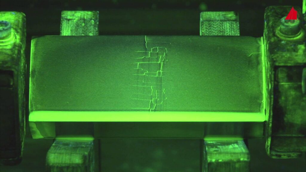
Dye penetrant inspection (DPI), also called liquid penetrant inspection (LPI) or penetrant testing (PT), is a widely applied and low-cost inspection method used to locate surface-breaking defects in all non-porous materials (metals, plastics, or ceramics). The penetrant may be applied to all non-ferrous materials and ferrous materials, although for ferrous components magnetic-particle inspection is often used instead for its subsurface detection capability. LPI is used to detect casting, forging and welding surface defects such as hairline cracks, surface porosity, leaks in new products, and fatigue cracks on in-service components.

DPI is based upon capillary action, where low surface tension fluid penetrates into clean and dry surface-breaking discontinuities. Penetrant may be applied to the test component by dipping, spraying, or brushing. After adequate penetration time has been allowed, the excess penetrant is removed, a developer is applied. The developer helps to draw penetrant out of the flaw where a invisible indication becomes visible to the inspector. Inspection is performed under ultraviolet or white light, depending upon the type of dye used – fluorescent or nonfluorescent (visible).

Dye Penetrant Testing

Dye penetrant inspection (DPI), also called liquid penetrant inspection (LPI) or penetrant testing (PT), is a widely applied and low-cost inspection method used to locate surface-breaking defects in all non-porous materials (metals, plastics, or ceramics). The penetrant may be applied to all non-ferrous materials and ferrous materials, although for ferrous components magnetic-particle inspection is often used instead for its subsurface detection capability. LPI is used to detect casting, forging and welding surface defects such as hairline cracks, surface porosity, leaks in new products, and fatigue cracks on in-service components.

DPI is based upon capillary action, where low surface tension fluid penetrates into clean and dry surface-breaking discontinuities. Penetrant may be applied to the test component by dipping, spraying, or brushing. After adequate penetration time has been allowed, the excess penetrant is removed, a developer is applied. The developer helps to draw penetrant out of the flaw where a invisible indication becomes visible to the inspector. Inspection is performed under ultraviolet or white light, depending upon the type of dye used – fluorescent or nonfluorescent (visible).

Visual Testing

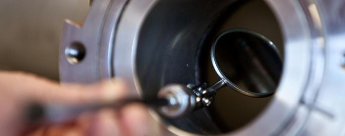
It is one of the most common and most powerful means of non-destructive testing. Visual testing requires adequate illumination of the test surface and proper eye-sight of the tester. To be most effective visual inspection does however, merit special attention because it requires training (knowledge of product and process, anticipated service conditions, acceptance criteria, record keeping, for example) and it has its own range of equipment and instrumentation. 

It is also a fact that all defects found by other NDT methods ultimately must be substantiated by visual inspection. VT can be classified as Direct visual testing, Remote visual testing and Translucent visual testing. The most common NDT methods MT and PT are indeed simply scientific ways of enhancing the indication to make it more visible. Often the equipment needed is simple for internal inspection, light lens systems such as bore scopes allow remote surfaces to be examined. More sophisticated devices of this nature using fibre optics permit the introduction of the device into very small access holes and channels. Most of these systems provide for the attachment of a camera to permit permanent recording.

SITAS NDT material testing facility contains light meters, welding gauges, magnifiers, lenses, other measuring instruments and equipments for precise control of surface quality. Our NDT inspectors, engineers and technicians are qualified to NDT Level I, II as per written practice prepared according to ASNT recommended practice SNT-TC-1A and in-house ASNT NDT Level IIIs for providing inspection and consulting services.

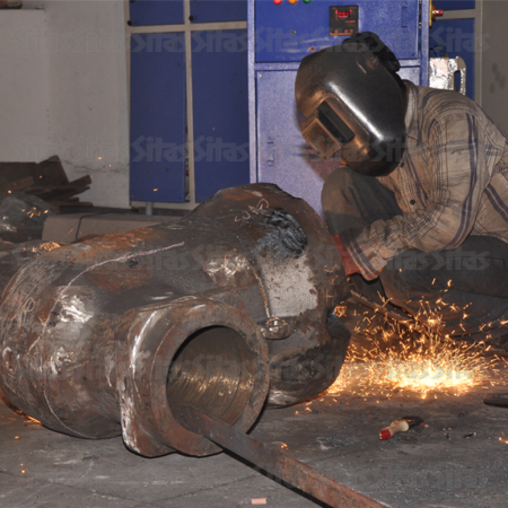
Upgradation of Casting

SITAS has full-fledged facilities and qualified welders for up-gradation of carbon steel, alloy steel and stainless steel castings. Radiographs will be evaluated to the required standards immediately and repairs / up-gradation will be undertaken. Pre heating of casting are done as per the specification using per heating furnaces. If required the casting are send for STRESS RELEVING in the furnance available with us.

SITAS has been already carrying out Radiography and up-gradation work for a few giant organizations like M/s. Bharat Heavy Electricals Limited, M/s AUDCO India Limited, Units at Manapakkam, Kanchipuram and Maraimalainagar, M/s. The KCP Limited, M/s. Peekay Steel Castings Limited, M/s. Sanamar Alloy Castings Limited, Viralimalai, M/s. Aruna Machine Tools Limited etc. to the entire satisfaction of the Inspectors and Clients.